Part 7: Fiber Optic Bundles
Overview
 For many spectroscopic applications, proper sampling requires more than just a simple fiber optic patch cord. In cases that require you to measure various samples simultaneously or those that require improved signal to noise ratio (as in the case of weak signals), the use of fiber optic bundles are required. In this section, we will discuss the advantages and disadvantages of some common fiber optic bundle configurations.
Fiber Optic Bundles:
A fiber optic bundle is defined as any fiber optic assembly that contains more than one fiber optic in a single cable. The most common example of a fiber optic bundle is known as a bifurcated fiber assembly. The goal of using a bifurcated fiber assembly is either to split a signal or to combine signals. Figure 7-1 shows an example of a typical bifurcated fiber assembly.

Figure 7-1 Example of a Bifurcated Fiber Assembly
Some of the most common applications for bifurcated fiber assemblies are those that require you to direct light from a sample into two different spectrometers. This is generally used to extend the spectral coverage of the measurement, either to maintain higher resolution, or to cover an extended range. For example, if someone is looking to make a broadband measurement from 350 – 1700nm, they need to use both an InGaAs and a Si detector array. By using a bifurcated fiber assembly with one UV fiber and one NIR fiber to direct light into each spectrometer, they can make a simultaneous measurement. Figure 7-2 shows an example spectrum of this type of measurement.

Figure 7-2 Spectrum of a Tungsten Halogen Lamp from 350 – 1700nm
A bifurcated fiber can also be used to couple the signal from multiple samples into the same spectrometer. When using a bifurcated fiber in this fashion, only one sample can emit light at a time, or special care should be taken to make sure the signals do not have spectral overlap.
The same basic principal and applications can be scaled up to trifurcated and quadfurcated fiber assemblies as well. An example of a trifurcated fiber assembly is shown in Figure 7-3 below.

Figure 7-3 Trifurcated Fiber Assembly
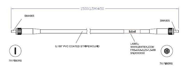
Another common bundled fiber optic assembly is called a “round to slit” configuration. This configuration consists of multiple small core fibers (typically 100µm) that are put into one fiber assembly with fibers bundled tightly in a circular fashion on one end, and stacked linearly on top of each other on the other end. The end with fibers stacked linearly on top of one another form a pattern to match the entrance slit of the spectrometer, as shown in Figure 7-4 below.

Figure 7-4 “Round to Slit” Fiber Optic Bundle
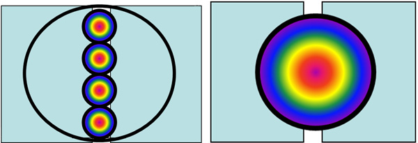
This configuration allows for much higher throughput into the spectrometer, as opposed to simply using a larger core fiber. As shown in Figure 7-5 below, when a large core fiber is placed in front of the entrance slit of a spectrometer, the majority of the light is vignetted and doesn’t make it into the spectrometer. By contrast, when the smaller fibers are stacked along the entrance slit, significantly more light enters into the spectrometer. This allows for much higher sensitivity and signal to noise, while maintaining resolution, since the slit can remain relatively narrow.

Figure 7-5 Comparison of Stacked Fiber to Single Large Core Fiber
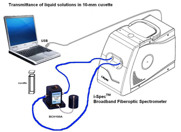
When using a fiber optic assembly with a slit configuration, it is important to remember two important details. First, in order to get any benefit from the fiber stacking, a cylindrical lens must be used to prevent the vast majority of the light to be imaged above and below the detector. Second, it is important to properly align the fiber stack to the entrance slit, which can be done by shining light into the round end of the assembly and monitoring the signal as the fiber is rotated in the SMA905 connection port. When peak signal is achieved, the fiber can then be screwed down to lock the position. One very common application using this kind of fiber optic assembly is NIR transmission spectroscopy, where there are very few photons and photon energy is extremely low. An example of a transmittance setup is shown below in Figure 7-6.

Figure 7-6 Example Transmittance Setup Utilizing a “Round to Slit” Fiber Bundle
By combining various combinations of single, round, and stacked configurations with regular, bifurcated, trifurcated, and quadfurcated fiber assemblies, there are countless options available to suit any application. In the next section, we will discuss how to combine fiber bundles with other various opto-mechanical components to create more specific applications.
Browse our extensive line of spectrometers.
Browse our spectrometer accessory line.
Submit your questions using the “Request Quote or Info” button above, or call us at (302) 368-7824.


